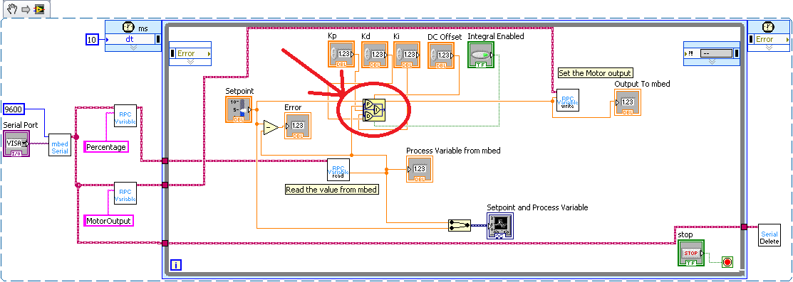

The PID VIs express the proportional component in terms of controller gain. Proportional action is the controller gain times the error, as shown in the following formula: K is the index of the sampled signal at time k* t The following formula represents the current error used in calculating proportional, integral, and derivative action: Refer to the National Instruments website at ni.com for more information about the Control Design and Simulation Module. You do not need the Control Design and Simulation Module to build PID controllers. However, the PID VIs implement PID controllers for you. Note Constructing a simulation diagram like the one in the previous image requires the LabVIEW Control Design and Simulation Module. The following simulation diagram represents the PID implementation provided by the basic PID VIs: The PID Advanced and PID Advanced Autotuning VIs use extended formulas with more advanced optional features. Note The following formulas apply to most VIs on the PID palette. To implement a PID controller, LabVIEW requires the algorithm to sample the input signals and discretize the integral and derivative action. This following sections describe how the basic PID VIs (not including PID Advanced, PID Advanced Autotuning, and other VIs with advanced options) implement the PID algorithm, and the assumptions and transformations necessary to implement the PID controller. Implementing the PID Algorithm with the PID VIs


 0 kommentar(er)
